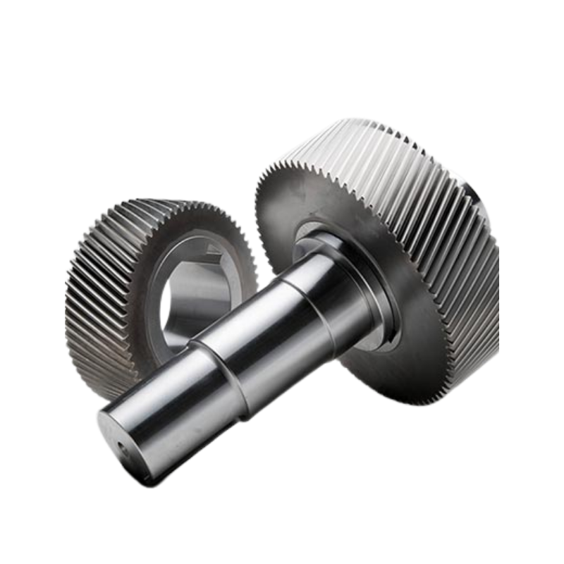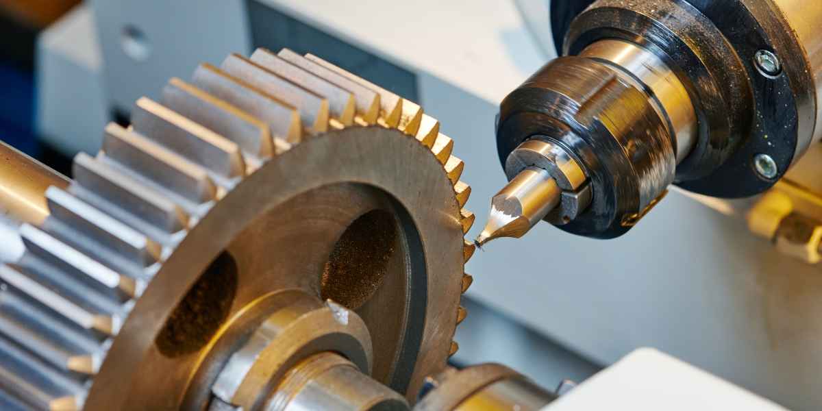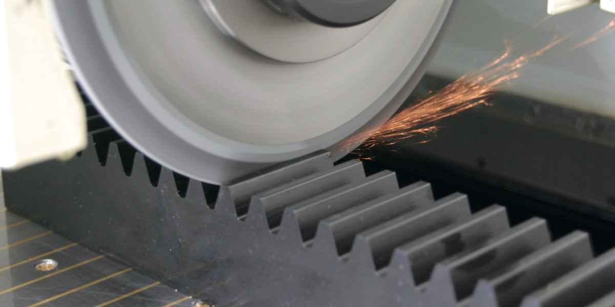
Tag: gear comparison

  • Worm Gear vs Bevel Gear: Efficiency, Self-Locking & Selection​

    Himax Gear precision worm and bevel gear manufacturing facility
    Himax Gear manufactures worm, bevel, miter and spiral bevel gears in steel, bronze and engineering plastics for global transmission OEMs.

    When a design has to turn power through 90° and change speed at the same time, two gear types usually land on the shortlist: the worm gear and the bevel gear. They look nothing alike and they behave nothing alike. A worm set can deliver a 100:1 reduction in a single stage and then lock itself against back-driving; a bevel set ships torque cleanly around a right-angle corner at near-spur efficiency. Pick the wrong one and you either burn efficiency you cannot spare or lose the self-locking safety feature your lift depends on.

    This guide compares tooth action, efficiency, self-locking, ratio range and cost, then gives you a decision checklist you can defend in design review instead of guessing.

    Table of Contents

    What Is a Worm Gear?

    A worm gear is a screw (the worm) meshing with a worm wheel — a gear whose teeth are cut to match the worm’s lead angle. The two shafts are non-intersecting and usually at 90°. As the worm turns, its thread advances the wheel by one tooth per input revolution on a single-start worm, which is exactly why a small input rotation produces a large output reduction. That geometry is the worm’s whole personality: enormous ratios in one compact envelope.

    Worm sets are the default choice wherever a high reduction and a right-angle layout must live in a small package — think conveyor drives, gate operators, lift jacks and tuning stages. Browse our full range of precision worm gear sets (bronze worm wheels paired with hardened steel worms, module 0.5–10).
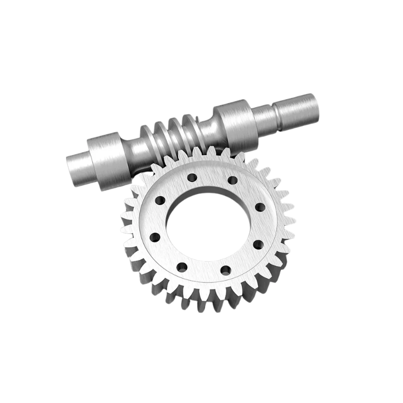
    Worm gear set with steel worm and bronze worm wheel
    Figure 1 — A worm set: a hardened steel worm driving a bronze worm wheel. A single stage can reach 100:1 reduction.

    What Is a Bevel Gear?

    A bevel gear has teeth cut on a conical blank so that two shafts meeting at an angle — typically 90°, but any angle is possible — can transmit motion. Straight bevels are the simple, low-cost form. Spiral bevels have curved, angled teeth that engage gradually, giving lower noise and higher load capacity, much like the helical-versus-spur story you already know from our spur vs helical guide.

    Bevels roll more and slide less than worms, so they run at 95–98% efficiency and handle high speed and high torque without the heat penalty. The trade-off is a modest ratio per mesh — usually up to about 6:1 without adding a second reduction stage — and a higher cutting/inspection cost for spiral forms. For intersecting right-angle drives, see our bevel gear series and the 1:1 miter gears for simple right-angle speed transfer.
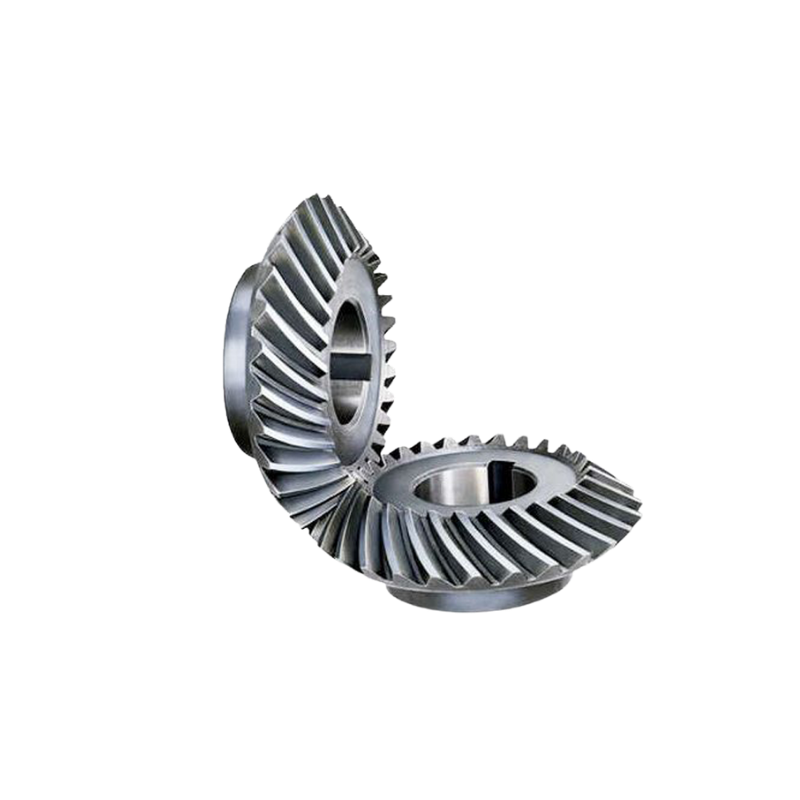
    Spiral bevel gear with angled curved teeth for right-angle power transfer
    Figure 2 — A bevel gear transmits torque between intersecting shafts; spiral teeth engage gradually for low noise.

    Worm Gear vs Bevel Gear: Side-by-Side Comparison

    FactorWorm GearBevel Gear
    Shaft arrangementNon-intersecting, offset 90°Intersecting, 90° (or other angle)
    Typical ratio per stageUp to 100:1 (single stage)Up to ~6:1 (single mesh)
    Efficiency30–90% (slides, runs warm)95–98% (rolls)
    Self-lockingPossible (shallow lead angle)No
    NoiseLow when lubricatedLow–moderate (spiral = quiet)
    Speed capabilityLow–moderateHigh
    Back-drivingPrevented (self-locking)Free
    Relative costModerate (bronze wheel adds cost)Higher for spiral bevel
    Typical useLifts, gates, jacks, conveyors, indexingDifferentials, power tools, right-angle gearmotors
    Right-angle gearbox combining worm or bevel stages with downstream spur and helical stages
    Figure 3 — Most practical right-angle reducers combine a worm or bevel first stage with spur/helical stages downstream. Choose the first stage with the checklist below.

    Self-Locking: The Worm’s Killer Feature

    Self-locking is what makes worm gears special. When the worm’s lead angle is shallow enough that the friction angle exceeds it, the worm wheel cannot drive the worm backward — the mechanism holds a load with no brake. This is why worm gears appear in hoists, lifts, jacks and gate operators: a dropped load cannot spin the input shaft.

    The catch is efficiency. A self-locking worm is the least efficient form, often 30–50%, because the same shallow lead angle that prevents back-driving also maximizes sliding. If you do not need self-locking, a steeper lead angle (or a non-self-locking worm) recovers efficiency toward 90% — but you then need a brake or counterweight to hold position. Design the lead angle to the requirement, not by default.

    Decision Checklist: Which One Do You Need?

    Work through these in order. The first constraint that points to one type usually wins:

    1. Must the load hold position with no brake? → Choose worm (self-locking).
    2. Is efficiency or heat a hard constraint? → Choose bevel (95–98%, runs cool).
    3. Is the ratio above ~6:1 from a single mesh? → Choose worm, or a bevel plus a second reduction stage.
    4. Are shafts intersecting exactly at 90° in a tight package? → Choose bevel or miter (1:1).
    5. Is the duty high-speed or high-cycle? → Choose bevel; worms wear faster under continuous load.
    6. Is it low-duty, low-ratio, cost-first, right-angle? → Choose straight bevel or miter.

    When Worm Gears Win

    • Hoists, lifts, jacks and gate operators where self-locking is a safety feature
    • Tuning and positioning stages where back-driving is undesirable
    • Compact high-ratio reductions in a single envelope
    • Low-duty, intermittent, cost-sensitive right-angle drives
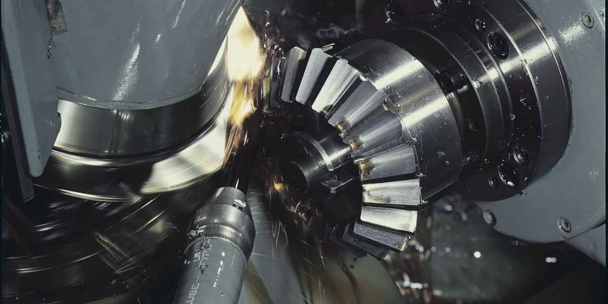
    Worm reducers assembled for material-handling and automation applications
    Figure 4 — Worm reducers in material handling and automation, where self-locking prevents runaway under load.

    When Bevel Gears Win

    • Automotive differentials and power take-offs
    • High-speed power tools and right-angle gearmotors
    • Continuous-running right-angle drives where efficiency matters
    • 1:1 right-angle transfers (miter gears)
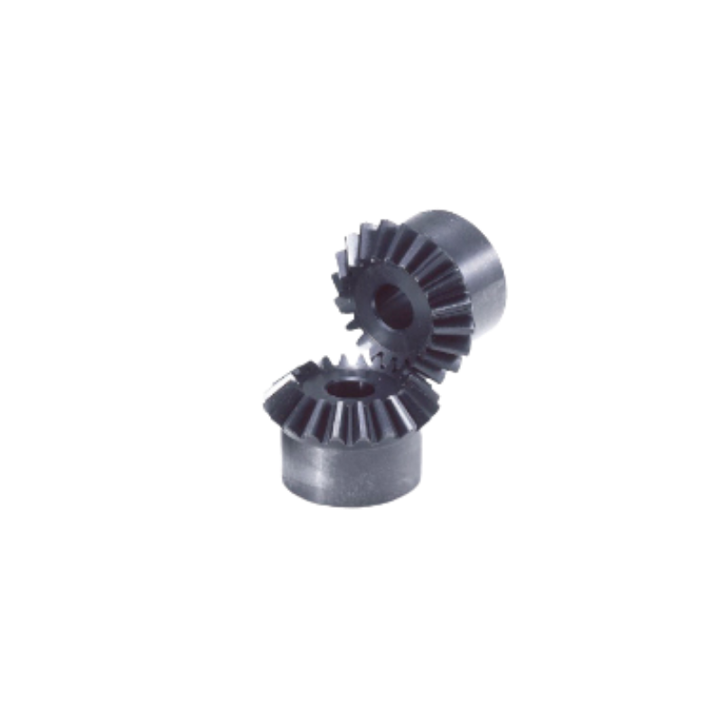
    Miter gears, a 1:1 bevel variant for right-angle speed transfer
    Figure 5 — Miter gears, a 1:1 bevel variant, are the standard for right-angle speed transfer without a ratio change.

    Frequently Asked Questions

    Which is more efficient, worm or bevel gear?

    Bevel gears are far more efficient — about 95–98% versus 30–90% for worm sets. Worm efficiency drops with ratio and especially with self-locking designs, because shallow lead angles maximize sliding contact.

    What does self-locking mean in a worm gear?

    Self-locking means the worm wheel cannot drive the worm backward, so the mechanism holds a load without a brake. It occurs when the worm’s lead angle is shallow relative to the friction angle. The cost is low efficiency, often 30–50%.

    Can a bevel gear replace a worm gear?

    Only if you do not need self-locking and your ratio fits a single bevel mesh (about up to 6:1) or you add a second reduction stage. A bevel cannot hold position against back-driving the way a self-locking worm can, so lifting and holding applications still need the worm — or an external brake.

    When should I use a worm gear instead of a bevel gear?

    Use a worm when you need a large single-stage reduction (roughly 20:1–100:1), self-locking, or a compact right-angle package and can tolerate lower efficiency and some heat. If efficiency and speed dominate, reach for a bevel.

    Why do worm gears run hotter than bevel gears?

    Severe sliding contact at the worm-wheel mesh dissipates more power as heat than the rolling action of a bevel mesh. Proper lubrication, correct oil viscosity and appropriate derating are essential; bevels roll more and stay cooler under the same load.

    Get the Selection Table

    Want the numbers on one sheet? We’ve built a Worm vs Bevel selection table — ratio limits, efficiency curves and material notes side by side. Send us your shaft angle, required ratio, torque and duty cycle, and our engineering team will specify the right set plus the exact module, material and hardness. Request the selection table and a custom gear quote and we’ll respond with a datasheet and RFQ number.

    Himax Gear is a China-based precision gear manufacturer, ISO 9001:2015 certified, producing worm, bevel, miter, helical, spur and rack gears since 1995 (founding year to be confirmed). For gearing standards referenced above, see the AGMA resource library. Learn more on our About page.
  • Spur Gear vs Helical Gear: Which to Choose? | Himax Gear

    Spur Gear vs Helical Gear: Which to Choose? | Himax Gear

    Spur Gear vs Helical Gear: Which Should Your Design Use?

    Himax Gear precision gear manufacturing facility
    Himax Gear produces both spur and helical gears in steel, bronze and engineering plastics for global transmission OEMs.

    Specifying a gear train usually comes down to one early decision: do you use a spur gear or a helical gear? Both transmit motion between parallel shafts, both come in steel, bronze or plastic, and both are stock items at any spur gear supplier. But the way their teeth engage changes everything about noise, load capacity, efficiency and cost.

    This guide gives you a side-by-side comparison and a practical decision checklist, so you can justify the choice in your design review instead of guessing.

    Table of Contents

    What Is a Spur Gear?

    A spur gear has straight teeth cut parallel to the axis of rotation. When two spur gears mesh, the full face width of each tooth makes contact at once. That sudden, line-on-line engagement is simple and cheap to manufacture, but it creates an impact load every time a tooth enters mesh.

    Spur gears dominate low-speed, low-noise-budget-insensitive applications: appliance drives, simple reducers, conveyor indexing, and any design where cost per unit matters more than acoustic comfort.

    See our full range of precision hardened steel spur gears (module 0.5–10, DIN 6 / AGMA 11 available).

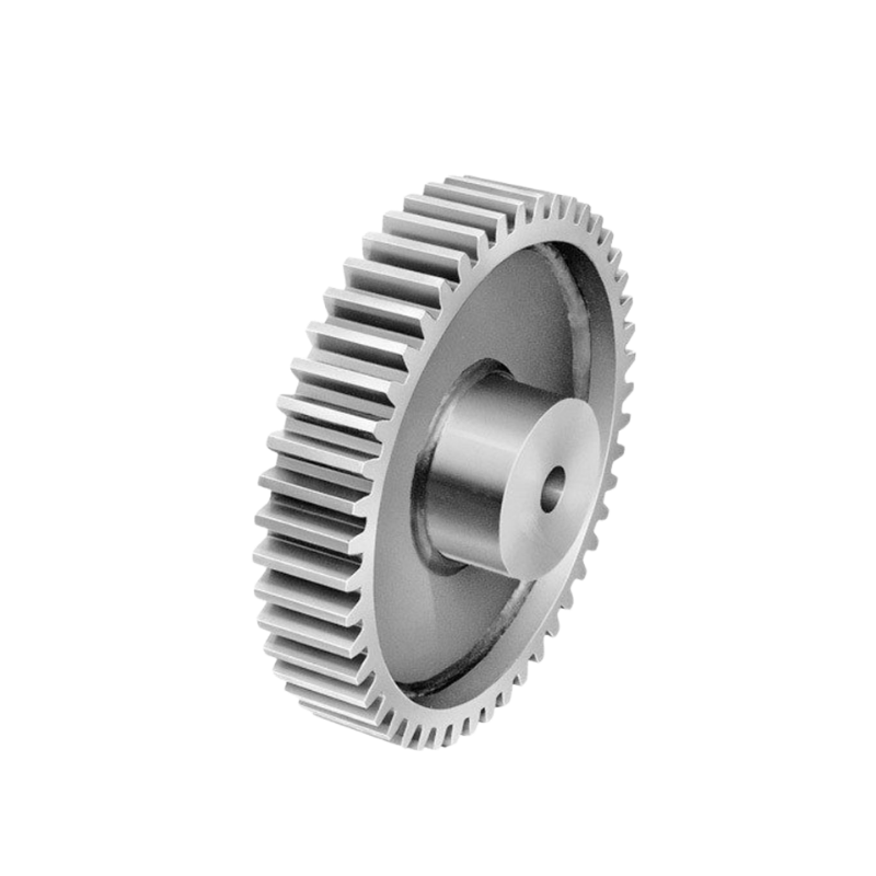
    Precision hardened steel spur gear with straight teeth
    Figure 1 — A typical hardened steel spur gear. Straight teeth keep manufacturing simple and cost low.

    What Is a Helical Gear?

    A helical gear has teeth cut at an angle (typically 15°–30° from the axis). The angled teeth engage gradually — one corner of the tooth touches first, then the contact line sweeps across the face. That progressive engagement removes the impact spike you get with spur gears.

    The trade-off: the helix angle produces an axial thrust force, so a helical stage needs thrust bearings (or a double-helical / herringbone design that cancels the thrust). Helical gears also cost more to cut because the hob must be aligned to the helix angle and the geometry is harder to inspect.

    For high-speed and high-load drives, browse our helical gear series built for automotive and industrial power transmission.

    Helical gear with angled teeth for quiet high-speed transmission
    Figure 2 — A helical gear. The angled teeth engage gradually, cutting noise and raising load rating.

    Spur Gear vs Helical Gear: Side-by-Side Comparison

    FactorSpur GearHelical Gear
    Tooth geometryStraight, parallel to axisAngled 15°–30° (helix)
    EngagementFull face contacts at once (impact)Gradual, sweeping contact line
    Noise & vibrationHigher, worse at speedLow — quiet even at high RPM
    Load capacityModerateHigher (more teeth in contact)
    Axial forceNonePresent — needs thrust bearing
    Mechanical efficiency98–99%96–98% (loss)
    Relative costLow (baseline)+20–40% typical
    Typical useLow-speed, cost-sensitive, appliancesAutomotive gearboxes, turbines, high-speed drives
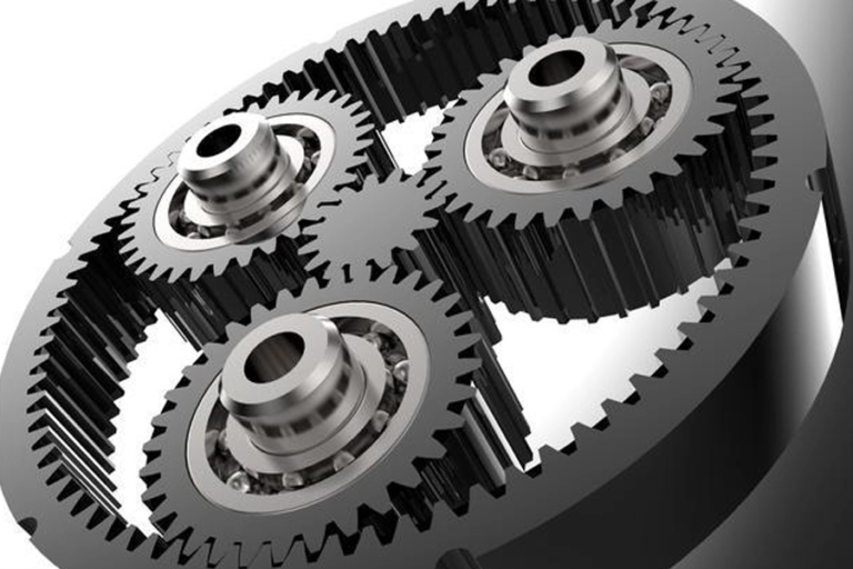
    Industrial gearbox combining spur and helical gear stages
    Figure 3 — Most practical gearboxes mix stages: a helical stage for the high-speed input, a spur or bevel stage for the output. Pick the stage type with the checklist above.

    Decision Checklist: Which One Do You Need?

    Work through these in order. The first “yes” that points to helical usually wins:

    1. Is pitch-line speed above ~10 m/s (≈ 2,000 RPM on a small gear)? → Choose helical. Spur noise and wear climb sharply past this.
    2. Is acoustic noise a spec item (office equipment, in-cabin automotive, medical)? → Choose helical.
    3. Is the transmitted torque high relative to package size? → Choose helical (more teeth share load).
    4. Is there no room / budget for thrust bearings? → Choose spur.
    5. Is this a low-speed, cost-first design (appliance, toy, simple actuator)? → Choose spur.
    6. Does the design reverse load frequently? → Either works; helical’s gradual engagement is gentler on reversal, but verify backlash spec.

    When Spur Gears Win

    • Low-speed, manually operated or intermittent drives
    • Cost-sensitive high-volume products where noise is not a spec
    • Designs with no axial space for thrust bearings
    • Easy inspection / reverse-engineering of legacy gearboxes
    CNC machine tool axis drive where simple spur gears suit low-noise-budget designs
    Figure 4 — Simple, low-speed machine-tool axes are a natural fit for low-cost spur gears.

    When Helical Gears Win

    • Automotive transmissions and differentials
    • Industrial drives running continuously at speed
    • Quiet servo and robotics actuators (see our gearbox range)
    • High-torque reducers where package size is fixed
    Automotive transmission using helical gears for quiet operation
    Figure 5 — Automotive transmissions are the textbook helical-gear application: high speed, high torque, and a strict noise budget.

    Frequently Asked Questions

    Which is more efficient, spur or helical gear?

    Spur gears are marginally more efficient — about 98–99% versus 96–98% for helical. The difference comes from sliding contact along the helix angle in helical meshes. In most drives the noise and load benefits of helical far outweigh the 1–3% efficiency loss.

    Why are helical gears quieter than spur gears?

    Spur teeth engage the full face width simultaneously, causing an impact load and a characteristic “gear whine.” Helical teeth engage gradually at a corner and the contact line sweeps across, so the load ramps up smoothly. Less impact means less vibration and lower radiated noise, especially above 2,000 RPM.

    Are helical gears stronger than spur gears?

    Generally yes, for the same size and material. The angled teeth keep more tooth pairs in contact at once, spreading load over a larger area. That higher contact ratio raises both load capacity and fatigue life — which is why helical gears are the default in automotive and turbine drives.

    Can I directly replace a spur gear with a helical gear?

    Not as a drop-in swap. A helical gear generates axial thrust, so the shaft and bearings must be redesigned to handle it. You also need matching helix angle and hand (left/right) on the mating gear, and the centre distance stays the same only if module and tooth count are identical. Treat it as a re-design, not a substitution.

    Which costs more to manufacture?

    Helical gears typically cost 20–40% more than an equivalent spur gear. The premium covers helix-aligned hobbing, harder inspection, and the thrust-bearing hardware the assembly now requires. For low-speed, cost-first products, spur remains the economical choice.

    Get a Custom Quote

    Still deciding? Send us your shaft distance, torque, speed and noise target and our engineering team will specify spur vs helical — and the exact module, material and hardness — for your drive. Request a custom gear quote and we’ll respond with a datasheet and RFQ number.

    Himax Gear is a China-based precision gear manufacturer, ISO 9001:2015 certified, producing spur, helical, bevel, worm and rack gears since 1995 (founding year to be confirmed). Learn more on our About page.